
Charged Reviews · Quick reference
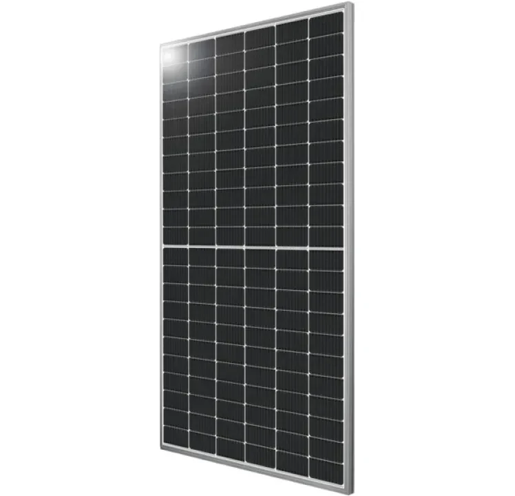
Silfab Solar ZB SIL 520 XM
- Brand
- Silfab Solar
- Model
- ZB SIL 520 XM
- SKU / part number
- ZB SIL 520 XM[1]
- Category
- Solar panels
Electrical at STC
| Rated output (STC) | 520 W[1]Provisional |
|---|---|
| Module efficiency | ? |
| Voltage at max power (Vmp) | ? |
| Current at max power (Imp) | ? |
| Open-circuit voltage (Voc) | ? |
| Short-circuit current (Isc) | ? |
| Power tolerance | ? |
Temperature and system limits
| Temperature coefficient, Pmax | ? |
|---|---|
| Temperature coefficient, Voc | -0.24 %/°C[3] |
| Temperature coefficient, Isc | ? |
| Maximum system voltage | 1,500 V[4] |
| Maximum series fuse | 30 A[4] |
| NOCT / NMOT | ? |
| Rated output at NMOT | ? |
| Operating temperature | ? |
Cells and construction
| Cell technology | ? |
|---|---|
| Cell count | ? |
| Bifacial | Yes[1]Provisional |
| Bifaciality | ? |
| Frame | Anodized Aluminum (Silver)[3] |
| Front glass | 3.2 mm high transmittance, tempered, antireflective coating[3] |
| Rear surface | High durability, superior hydrolysis and UV resistance, multi-layer dielectric film, transparent PV backsheet[3] |
| Panel format | ? |
Mechanical and connections
| Dimensions | ? |
|---|---|
| Weight | ? |
| Connectors | ? |
| Cable length | ? |
| Junction box rating | ? |
| Mounting | ? |
| Design load, front | ? |
| Design load, rear | ? |
Installation (from the manual)
Conductors
| Cable bending radius / connector notes | Cable bending radius should be at least 60 mm (2 3/8”).[4] |
|---|
Clearances and orientation
| Mounting methods and clamp zones | LONG EDGE MOUNTING L Design Load Test Load 0 - 175 +1066 / -933 +1600 / -1400 175 - 425 +1333 / -1200 +2000 / -1800 425 - 525 +1600 / -1600 +2400 / -2400; LONG EDGE MOUNTING WITH CENTER SUPPORT L Design Load Test Load 0 - 175 +2000 / -1600 +3000 / -2400 175 - 400 +2400 / -2400 +3600 / -3600; SHORT EDGE MOUNTING L Design Load Test Load 0 - 300 +933 / -800 +1400 / -1200; SHORT EDGE MOUNTING WITH CENTER SUPPORT L Design Load Test Load 0 - 300 +2400 / -2400 +3600 / -3600; SHORT EDGE PARALLEL TO RAILS L Design Load Test Load 325 - 475 +3600 / -2400 +5400 / -3600 475 - 575 +2400 / -1600 +3600 / -2400; LONG EDGE PARALLEL TO RAILS L Design Load Test Load 325 - 425 +1600 / -1600 +2400 / -2400; LONG EDGE TRACKER MOUNTING L Design Load Test Load 400 +1200 / -1200 +1800 / -1800 1300 +1600 / -1600 +2400 / -2400 400 + 1300 +1733 / -1733 +2600 / -2600; M6 or 1/4” corrosion-resistant bolts, nuts, and a locking feature are required; are permitted for the following Silfab Solar product lines: SIL-XXX BK/BG/HC/HC+/QD/HN/HM/QM/XM/ XM+/XL.[4] |
|---|
Grounding
| Grounding | A UL listed grounding lug can be bonded to the grounding hole located on the bottom flange of Silfab Solar’s module frame.; The grounding lug should be attached to the frame grounding hole using stainless steel hardware (bolt, serrated flange nut, toothed lock washer, KEPS nut, etc).; Silfab Solar modules may be bonded to a racking or rail system using an integrated grounding method certified to UL 2703.[4] |
|---|
Not in the manual: Torque
Page 1 of 2 · Installation values · ? means nothing is recordedAggregated, often community-reported information, not official documentation. Do not rely on it for installation, purchase or compliance decisions; always confirm values with the manufacturer’s official documentation. Charged Reviews accepts no responsibility for errors.