
Charged Reviews · Quick reference
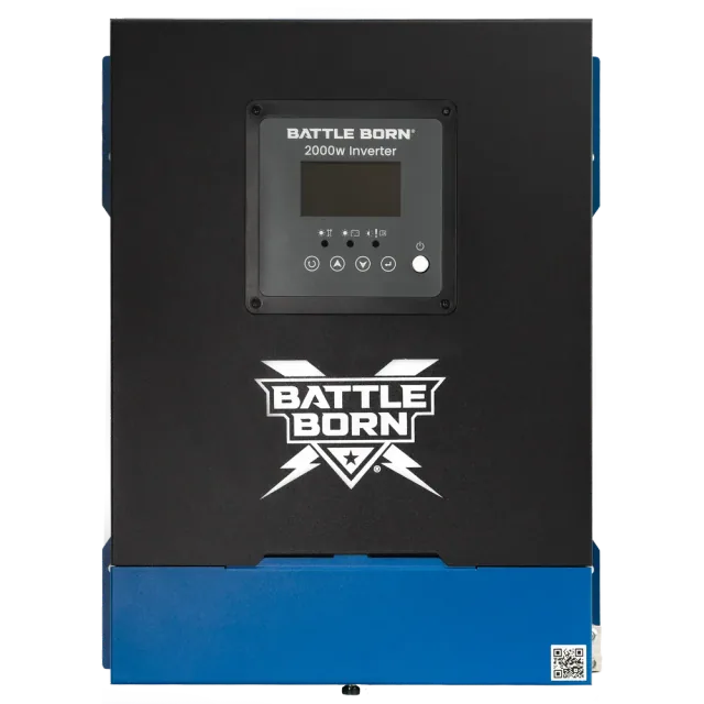
Battle Born 2000W Inverter
- Brand
- Battle Born Batteries
- Model
- BBI2000
- SKU / part number
- BBI2000[1]
- Category
- Inverters
AC output
| Continuous output | 2 kW[1]Calculated |
|---|---|
| Peak output | ? |
| AC configuration | ? |
| AC output voltage | 120 V[1] |
| AC frequency | 60 Hz factory default; adjustable to 50 Hz[5] |
| Grid pass-through | ? |
| Maximum output per leg | ? |
Battery
| Battery voltage | 12 V[1] |
|---|---|
| Battery voltage range | Low battery cut-out voltage to 18.0 V DC[1] |
| Maximum charge current | ? |
| Maximum discharge current | ? |
| Battery-only output | ? |
| Maximum grid charging | ? |
| Compatible batteries / BMS | ? |
PV input
| PV array limit (connected) | ? |
|---|---|
| PV input limit (converted) | ? |
| Maximum PV voltage (Voc) | ? |
| MPPT voltage range | ? |
| MPPT trackers | ? |
| String inputs per MPPT | ? |
| PV current per MPPT | ? |
| PV short-circuit current | ? |
| PV startup voltage | ? |
Efficiency and modes
| Peak efficiency | ? |
|---|---|
| CEC weighted efficiency | ? |
| Battery conversion efficiency | ? |
| Grid / off-grid modes | Integrated automatic transfer switch, 30 A relay rating (24 A continuous); second AC output (L2) is a passthrough circuit that is live only when AC input is present[1] |
| Generator input | ? |
| Transfer time | 20 ms[1] |
| Idle consumption | ? |
| Parallel units | ? |
Communication and environment
| Communications | Removable, rotatable control panel; Battle Born mobile app; state of charge of Battle Born smart batteries shown on the remote panel[1] |
|---|---|
| Operating temperature | -20 to 60 °C[1] |
| Enclosure rating | ? |
| Operating noise | ? |
Mechanical
| Dimensions | 306 W × 101 H × 390 L mm[1] |
|---|---|
| Weight | 7.8 kg / 17.2 lb[1] |
Installation (from the manual)
Conductors
| Battery conductors | 2/0 AWG (cable length < 2 meter, ~6.5ft); 4/0 AWG (cable length 3-5 meter, 10-16ft)[5] |
|---|---|
| AC input conductors | AWG 10 (minimum wire gauge, AC-in)[5] |
| AC output conductors | AWG 10 (minimum wire gauge, AC-out-1 and AC-out-2)[5] |
| PV conductors | ? |
| Ground conductor | ? |
Protection
| AC input breaker | AC-in: 30 A fuse or circuit breaker[5] |
|---|---|
| AC output breaker | AC-out-1: 30 A; AC-out-2: 30 A (fuse or circuit breaker)[5] |
| Battery fuse or breaker | Recommended DC Fuse 250A[5] |
| PV disconnect | ? |
Clearances and orientation
| Installation clearances | Maintain at least 10 cm (4 in.) of clearance around the fan and cable connection side for cooling airflow.[5] |
|---|---|
| Mounting orientation | Allowed: Horizontally (on a shelf or deck); Horizontally upside-down; Side-mounted on a vertical wall. Not allowed: Vertical wall mount with vents facing up or down.[5] |
Grounding
| Grounding and neutral-ground bonding | The inverter/charger is a Class I device and requires a continuous connection to a protective ground.; A dedicated external grounding point is provided on the chassis.[5] |
|---|
Not in the manual: Torque, Communication
Page 1 of 2 · Installation values · ? means nothing is recordedAggregated, often community-reported information, not official documentation. Do not rely on it for installation, purchase or compliance decisions; always confirm values with the manufacturer’s official documentation. Charged Reviews accepts no responsibility for errors.